
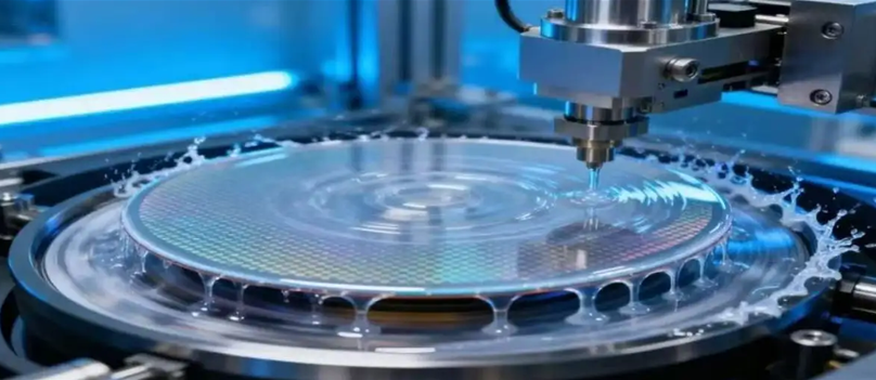
On the fab floor, you know how it goes: a 0.5°C drift at the inspection stage will move the photoresist profile, shift CD bias, and suddenly you’re staring at a lot that needs rework. Heat can’t be a wild card. It has to behave like a controlled process parameter.
What matters under the hood
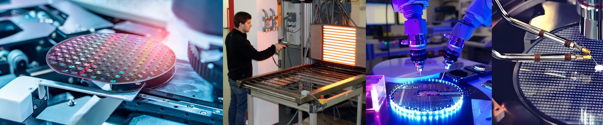
We built the inspection tool heater around ±0.1°C steady-state uniformity across the stage, and that comes from a low-thermal-mass design that responds fast. Quartz or ceramic heating elements are paired with a PID loop tuned for sub-second settling, so setpoint changes track clean—no overshoot. It’s cleanroom-compatible through and through: low-outgassing materials and sealed interfaces keep particle generation in check. The payoff is practical—repeatable soft bake and hard bake translate straight into stable lithography overlay and CD control.
Why this lands in inspection
In inspection, you run the same recipe across hundreds of wafers, often back-to-back. Thermal repeatability cuts metrology offsets and knocks out temperature-induced image artifacts that otherwise get flagged as false defects. The heater fits Class 1–100 cleanrooms with a zero-particle profile, so you’re not fighting yield loss from contamination. Fast ramp-to-setpoint shortens stage dwell and keeps throughput moving. Energy stays disciplined because the control algorithm trims idle power without sacrificing uniformity.
The things you’ll want to plan for
Installation comes down to mechanical clearances and thermal interface flatness—even a small mismatch can create local hot spots. The heater works with most inspection platforms, but if you’re integrating into legacy frames, expect a custom mount and a re-validation of the thermal control loop. Spec voltage and connector type up front to avoid field changes, and set calibration intervals so that ±0.1°C performance holds over time.